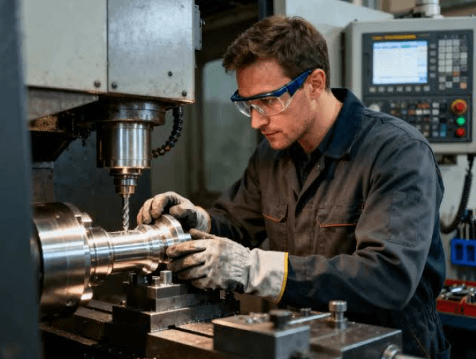
Precision chamfering machines and metal spindle liners solve different problems within the same CNC bar-machining process. A chamfering machine prepares the end of the raw bar so it can load, feed, and enter downstream equipment more reliably. A metal spindle liner then supports that bar inside the CNC lathe, limiting unnecessary movement while the material rotates.
Used together, these systems create a more controlled path from raw bar preparation through machining. Understanding why they work together starts with understanding what happens to the bar before and after it enters the lathe.
What Does a Precision Chamfering Machine Do?
A precision chamfering machine removes material from the end or edge of bar stock to create a controlled bevel, or chamfer.
Depending on the machine and tooling, bar chamfering equipment may also perform operations such as facing, turning, center drilling, or combined turning and chamfering. Machines can range from manually loaded equipment to semi-automatic and fully automatic systems.
One important advantage of dedicated bar chamfering equipment is that the bar itself may remain stationary while the cutting head rotates. For example, this approach is used by some manual chamfering machines to eliminate the need to rotate and support an entire long bar during the preparation operation.
The finished chamfer serves several possible purposes, but in CNC bar feeding, one of the most important is creating a controlled leading edge.
Why Chamfer the Bar Before It Enters a CNC Lathe?
Raw bar ends are not always ideal for automated or repeatable feeding. They may have burrs, sharp edges, saw-cut irregularities, or geometry that makes entry into a collet, guide, spindle liner, or other component less predictable.
A controlled chamfer creates a more gradual transition at the end of the bar.
For bar-feeding applications, a chamfer on the leading end can help the bar load more smoothly. JF Berns, for example, specifically identifies a 30-degree front chamfer as one method that can help improve bar loading in applicable bar-feeder setups. Some applications also require the bar end to be turned down when a collet-style pusher must fit over the material.
The exact chamfer angle and dimensions should still be selected for the application rather than treated as universal specifications.
Once the bar is prepared, however, the challenge changes. The next objective is controlling the material while it rotates.
What Does a Metal Spindle Liner Do?
A spindle liner reduces the effective inside diameter of a CNC lathe spindle or draw tube so that smaller-diameter bar stock receives additional support.
Without a liner, a relatively small bar may have substantial clearance inside a larger spindle or draw tube. Because the bar is clamped near the machining end, unsupported material extending behind the chuck can move as spindle speed increases.
That movement can contribute to bar whip, vibration, machining instability, and safety concerns.
A properly sized spindle liner reduces the amount of room available for the bar to move. JF Berns identifies 3 fundamental characteristics of effective spindle-liner performance:
- Correct clearance over the actual bar outside diameter
- Straightness of the spindle liner ID
- Rigidity of the liner and support system
Metal liners are particularly useful because their rigid construction provides a defined support path rather than allowing the liner itself to flex significantly with the rotating material.
How Do Precision Chamfering Machines and Metal Spindle Liners Work Together?
They function sequentially.
The chamfering machine prepares the bar for entry and feeding. The spindle liner controls the bar after it enters the CNC lathe and begins rotating.
A simplified production sequence looks like this:
- Raw bar stock is cut or selected for production.
- The leading bar end is precision chamfered.
- Additional turning or facing is performed when required by the feeding system.
- The prepared bar is loaded into the bar feeder, loader, or CNC lathe.
- The chamfered end helps guide the bar through the applicable feeding components.
- The metal spindle liner supports the bar inside the spindle or draw tube.
- The chuck secures the material, and the bar rotates during machining.
- The liner limits unnecessary movement of the unsupported portion of the bar.
The chamfering machine therefore improves the transition into the system, while the spindle liner improves control within the system.
That distinction explains why the 2 technologies complement each other.
Why Does Bar-End Geometry Matter to a Spindle-Liner Application?
A spindle liner depends on carefully controlled clearance around the bar outside diameter.
That does not mean the bar should fit tightly enough to interfere with feeding. Instead, the liner must provide adequate running clearance while still limiting unnecessary movement.
An irregular or heavily burred bar end can complicate entry into a controlled-clearance system. Precision chamfering removes the abrupt edge and creates a more predictable leading profile before the bar reaches the liner.
Chamfering is not a substitute for correct spindle-liner sizing, however.
A perfectly chamfered bar can still move excessively if the liner ID is too large. Likewise, a correctly sized spindle liner does not eliminate the value of properly preparing a rough or difficult bar end.
The 2 operations address different variables.
Why Are Metal Spindle Liners Well Suited to This Process?
Metal liners provide rigidity, measurable geometry, and durability within the rotating portion of the process.
These characteristics become important because effective bar control depends on maintaining the liner close to the intended centerline. A liner that moves or deflects can create additional freedom for the bar to move with it.
JF Berns’ comparison of metal and urethane spindle liners notes that steel designs can be straightened and their geometry verified. The company also points out that the material between support points remains rigid in a steel liner, whereas a more flexible liner material may deflect when subjected to forces from a rotating bar.
Metal liners can also be manufactured in thin-wall, extended, multi-piece, quick-change, and other machine-specific configurations when the application supports those designs.
The objective is not simply to put metal around the bar. It is to establish a straight, rigid, correctly sized, and securely mounted support system.
How Do Chamfering and Spindle Support Improve Process Consistency?
CNC bar machining involves several transitions.
The material has to move from storage or a bundle into a loader, through feeding components, into the spindle, through the liner, and ultimately into the workholding and machining area.
Problems at any one of those points can affect production.
Precision chamfering addresses the front end of that chain by producing a repeatable bar-end geometry. Depending on the tooling, dedicated chamfering equipment can produce chamfers, faces, turned sections, and other prepared features without relying on manual grinding.
The spindle liner addresses another part of the chain by controlling the relationship between the rotating bar OD and the available ID inside the spindle or draw tube.
Together, they reduce 2 sources of variability:
Entry variability: Burrs, sharp corners, or irregular bar ends can make loading less predictable.
Rotational variability: Excess clearance around the bar can allow unnecessary movement once the spindle accelerates.
Controlling both creates a more engineered material-handling process.
Does Chamfering Reduce Bar Whip?
Not directly.
Chamfering changes the geometry at the bar end. Bar whip is primarily associated with the dynamics of rotating, insufficiently supported bar stock.
The spindle liner is the component intended to address that problem inside the lathe.
Effective control depends on variables including bar-to-liner clearance, bar and liner straightness, liner rigidity, bar diameter and length, spindle speed, and overall machine configuration.
If the bar extends beyond the supported spindle-liner system, additional bar-support equipment may also be required. Unsupported rotating bar beyond the spindle can create a serious safety hazard.
When Does Turning and Chamfering Become Important?
Some feeding systems require more than a simple chamfer.
A collet-style bar-feeder pusher, for example, may need to grip or fit over the back end of the bar. In those applications, the bar may need to be turned down to create the required geometry.
Dedicated chamfering equipment can combine turning and chamfering into one preparation process when appropriate.
This illustrates a broader principle: bar preparation should be designed around the entire downstream system.
The correct question is not merely, “What chamfer should we put on this bar?”
Manufacturers should consider:
- CNC lathe make and model
- Bar diameter and actual outside diameter
- Bar length
- Material
- Bar feeder or loader configuration
- Pusher or collet requirements
- Spindle and draw-tube dimensions
- Spindle-liner clearance
- Required chamfer geometry
- Production volume
- Spindle speed
- Surface-finish requirements
- Existing vibration or bar-whip concerns
Those variables determine how the chamfering and support systems should be configured.
See also: The Mechanics of Technological Innovation
Why the Two Systems Are Designed Differently
At first glance, it may seem unusual that a precision chamfering machine can keep a long bar stationary while a CNC lathe deliberately rotates that same material at substantial speed.
The difference reflects the objective of each machine.
During chamfering, the goal is to machine the end of the bar. Rotating the cutting head while keeping the bar stationary can simplify the handling of long stock and eliminate the need to support an entire spinning bar during the chamfering operation.
During CNC turning, the process works differently. The workpiece rotates while cutting tools remove material.
That makes bar support much more important.
The metal spindle liner exists because the same bar that was safely stationary during preparation must now remain controlled while rotating inside the lathe.
In other words, each system is engineered around the motion required during its specific part of the manufacturing process.
Building a Better Bar-Machining Process
Precision chamfering machines and metal spindle liners should be viewed as complementary components of a controlled CNC bar-machining system.
The chamfering machine prepares the material by creating a consistent leading geometry and, when necessary, additional turned or faced features. The metal spindle liner then supports that prepared material inside the lathe, reducing excessive clearance and helping control bar movement during rotation.
Neither system replaces the other.
Chamfering improves how the bar enters and interfaces with feeding equipment. Spindle liners improve how the bar is supported once machining begins.
For manufacturers evaluating both technologies, the strongest approach is to engineer the process around the complete application rather than selecting either component in isolation. Machine configuration, material dimensions, feeding method, bar length, spindle speed, required chamfer, and support requirements should all be considered together.
Manufacturers such as JF Berns develop both precision chamfering equipment and machine-specific metal spindle liners, allowing these variables to be evaluated as parts of the same bar-processing system rather than unrelated accessories.